12.26.2015

Starting with "Quinntopia Metro"

Hello! And a belated "Merry Christmas"! Well, I have not made as much progress as I had hoped by now, but with the holiday preparations and all that, I have not had as much hobby time as I had thought! But this unplanned delay is a good thing as it gives me time to consider or reconsider how to accomplish different aspects.

Case in point is the "metro line".  The metro will be an elevated line that I am imagining will snake through the city.  As such, before any city planning can be done, the exact track layout for the two-track metro line needs to be determined (which is also constrained by the outer loops of the 'main line railways).

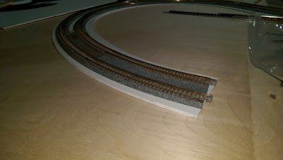
My original approach was to use Unitrack curves - the 216 and 249 radius curves -which would then connect to Atlas flex track for the non-curved sections. I decided not to use existing Kato viaduct sections as the walls are a bit too overwhelming and would block the trains.  I wanted something a bit different, so I knew I would be scratch-building some sort of viaduct/elevated structure.  So my original concept was to use 1/8" thick PVC foam board (one of my materials of choice!) as the base, and then mount the Unitrack to this material - with some sort of siding to make it look like an elevated trestle or viaduct system.
However, as I was browsing online various prototype photos of the U-bahn, Chicago El, NYC's elevated sections, I began to see the problem.  The Unitrack ballast just won't look quite right and is not really a feature of elevated track. So..what to do? I also notice that a lot of elevated sections tend to be nothing more than girders, ties, and rails. Not a lot of 'flat space'.

So what I decided to do was abandon Unitrack and go with some classic snap track - in this case I'll be using Minitrix's R1 and R2 radii curves (which also means much tighter curves at 194.6 and 228.2 radii - which should be better for my cityscape than the wider curves. I am a bit concerned that these might be TOO tight, but as this is going to be a metro system, it's not like I'll be running any TGVs or traditional passenger cars on this line - well, at least that option is gone now!).

So I started with a new plan for my viaduct. After several different attempts using various easily available and cost efficient materials, I ended up with a plan that will use Evergreen Scale Models 1/4" thick plastic strips along with 1/4# wooden dowels available at the hardware store.
Across these structure sections will rest 0.80x0.80 square styrene strips that will support the actual track.
I'm using a 17mm spacing between the ends of the ties for each track, which will be identical to the doubletrack spacing of Unitrack sections, which seems like a useful benchmark.
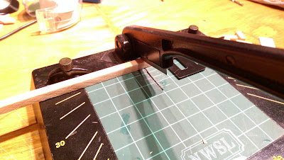
 Using my handy chopper (after a couple of years of gathering dust!) I'm back in business slicking strips of wood to make up the main structure!
And so, the initial straight section is complete!  If this approach works out, then I'll proceed to creating the curves and the station section using the same basic format.

12.13.2015

Benchwork Update

A quick update....I've been working non-stop for the past two weeks, so this weekend I finally got some time to put together the benchwork.  Of course, a trip to the local hardware store (and $196 and change)  was necessary to get the necessary 1/4" plywood sheets to cover the benchwork! And viola! I have the foundations for the new layout all set!
My plan is to lay out some track and see what I've got, then start figuruing out where the track will go.  I already know it's going to be a large loop, but with a significant sized modern city in the center, I don't think it will have that 'loop' feel.  

The plywood panels are only placed on the benchwork temporarily, as they will be removed and cut to allow for raised elevations for the city level.  I also expect to lay down at least a 1" base of styrofoam on the bottom level.  Maybe.  I really don't love working with that if I don't have too.  I may end up using risers for the roadbed and styrofoam surrounding it...we'll see.  The concept with this layout is going to be very urban, so not sure I'm going to need a lot of 'terrain' that would have natural rises and such.

This is starting to get fun!

11.28.2015

Benchwork By Mail!

The benchwork arrived yesterday! As I mentioned in my last post, I've decided to avoid something I'm neither good at (carpentry) or enjoy and bite the bullet and spend what would be the equivalent of several locos or a very expensive starter set and order some professionally cut, measured and prepared benchwork.

So I braved the cold weather in the garage and started to go through the box.  The box was smaller than I would have expected for all the materials and space this layout would ultimately take up, but it was quite heavy nonetheless - and it took a beating in transit as well, with one of the two outside corner curve sections having gotten cracked (I've contacted the supplier about this today to see if it can be replaced).
The rest of the materials I'm glad to see are in great shape. There are three 42"x48" and one 42"x12" modules.  This gives me a total dimension of 42" x 13" - with the additional 18" curve sections, I'll have nearly 14' of running space.
The material is a cabinet grade plywood which, for a variety of reasons explained at ModelRailroadBenchwork's website, are much better than anything that I could (or want!) to put together on my own! These are solid 3/4" wide sections of plywood with all the screw holes, access holes, and bolt holes already pre-drilled.
Assembly is easy - and actually quite quick! Instructions (and screws and bolts) were provided, so it only took me a few minutes to go from this....
To my first completely assembled module!
Since I was in the spirit of it, I kept going and put the other three modules together...and viola! Here is the foundation for the next Quinntopia!
I will still have to make some runs to the hardware store for the boards to connect the modules to my legs (re-using the 'yellow legs' of my previous layout, but now in a more neutral grey color!) as well as for the surface of the layout, but that's a lot less work than creating the cuts and measurements needed for this part. I'm super pleased with how this turned out and can't wait to get started on the next stage.

So far, I would have to say that if you can afford it (my total cost for all of the above, including shipping, was $460, plus $96 to have it shipped from Florida to Washington State) and want a sturdy benchwork and cannot do it yourself at any decent level of skill, this seems like a decent option!

11.17.2015

Quinntopia: The ReBoot!


The reboot is almost here. After several attempts to plan the layout with RRTrack, and essentially designing a layout that looks an awfully lot like old Quinntopia Version 2, I've decided to throw caution to the wind and start putting together a layout based on a few simple principles.  I can only move things around on the computer before too long, so I'm just going to be practical about it (I sort of have an idea of what I want anyway, the software is good for getting estimates on how much stuff I need to buy, and approximate ideas of space and so on).  Here's the main ideas:
  • I have to limit the scope. I liked the urban aspects of the old layout (and I think was one of the things that was most popular with viewers as well) so the idea of having any sort of natural landscape will be minimal.  
  • Since its going to be a very urban layout, Its going to be a city surrounded by several 'main lines'.  The question is...three, or an overwhelming four? I'm still not sure.  Four track main line means an 8 track total, which limits the city space, and can look a lot like a racetrack and not a city/train layout!
  • These lines split into several tracks for a large urban station and to provide some minimal storage (mostly for those annoying to assemble and disassemble TGV, ICE's and the like).  Again, I have to be realistic and probably reduce the main lines to three.
  • The rest? It will be City, City, and more city.
Still up for question is whether or not I try and run an elevated 'transit' line within the city it itself. This could be problematic.  My approach is to determine approximately how much space within the large oval of tracks I will have for the 'city' (the tracks will of course run around the perimeter, but will have a few gradual curves so it's not just straight tangents) and then works with various city block/building layouts to determine if a smaller, elevated, double-track line can be worked into the city.

Here's my (formerly yellow!) supports for the layout benchwork - now in a fresh color of neutral grey!
The dimensions will be around 42" by 14.5' feet long, or 1066 x 4419 long if we use the metric!

I've decided to invest decent money and have some professionally, pre-built benchwork made by an outfit called ModelRailroadBenchwork.com. It will be modular as well, so I can re-use these if a future move happens! I ordered my modules a week ago, so I'm already anxious to get them and set up the future layout!  No more hollow-core doors for me!

Of course, the real fun will be pulling out the structures from storage! Whoopee!
 That's it for now! I'm looking forward to a very fun, N scale focused winter!

11.14.2015

Paris

For my friends in France and the people of Paris, my heart is with you on this incredibly dark day.  It was an unspeakable evil.  I pray that it will be the last time that any of us have to witness this sort of horror again.


10.27.2015

Star Train CC 7100 Instruction / Product Manual

Hello fellow N-Scalers! A quick post from the land of ambiguous layout reboots to share the instruction manual for the Star Train CC 7100 locomotive.  I was recently sent an email asking "Where do you lubricate this thing".   So I dug through my boxes, found the manual, scanned it in, and am here to share it with the world (note that a Google search for "Star Train CC 7100" only results in a lot of frustration, so I'm just trying to do my part!).

Here is page 1 in all its glory (I think if you click on it, it should get bigger. At least, that's what my 'blogspot for dummies' manual says):
Here is the fascinating second page of the manual...(which includes the hard to find lubrication instructions at the bottom!):
And the third...


And the final page!
That's it for now...but I am actually working on the new layout!  Yes I am! You'll see! Soon....


5.25.2015

The Dark Age of Quinntopia - when will it end?

Hello fellow modelling enthusiasts of all scales and types!  Obviously, I have not been active on the old blog, or in the hobby for that matter, lately.  As this weekend is sort of the one year anniversary of the 'end of Quinntopia' I thought it might be nice to provide an update on "Quinntopia: The Reboot".

Except there isn't one. Yeah, I really have not made much progress.  I have had ambitions - and a few false starts - of using layout design software to create my next layout, but each time I keep creating the same layout I had before (and / or far larger than I really want) or too minimal and not at interesting enough to get motivated with the carpentry.

So...the dark ages of Quinntopia continue.

But I had a sort of epiphany...what if 'planning software' is my problem?  After all, the original Quinntopia began (and continued to grow) without any software planning (I did go back in and retroactively recreate it in RRTrack just so I could have a plan to work with). This led to a much faster creation to train-running time period, and was far more satisfying than a plan on a computer.

So I may take that approach. But not without any sort of limits - I sort of know what I want after my experiences with the original Quinntopia, so I plan to make a mental list of those things and be disciplined about sticking with them.  Some of those 'best practices' I established in my 'mistakes' post, for example, while it does not need to be mobile, it can't be permanent.  I don't want it so large that it dominates my entire room.  I want as much 'main line' for train running as possible, and finally, its an urban layout, so start with the city and work the tracks in and around the structures.

So here's my strategy: Start with a module that will fundamentally be the city - all the buildings, cars, and lighting that that entails.  From there, configure the tracks as if they were passing through an urban area.

Simple, right? Well, we'll see if simplicity is better motivator for getting a layout back in the world versus thinking about it!

On a more personal note, you may be surprised that the ruler of the kingdom of Quinntopia is a human just like everyone one else and was subject to distractions which kept him from the development of his benevolent dictatorship;  I found myself on the receiving end of one of those 'reduction in force' discussions last Fall.  Yes, I was 're-tooled' or something!   So for much of the quiet period this past year I was out networking and applying for new roles, etc....  The good news is that I am now gainfully employed again with a great, new employer.  The bad news is that the job requires more time and a bit longer commute than I previously had, so precious discretionary hours for hobby-related interests are a bit more difficult to find.

In the meantime, I hope you enjoyed the detailed and fascinating (and somewhat amazing) story of Terry's repair of a Rivarossi Chapelon locomotive that he has been sharing on this blog over the past couple of months.  It was fun to see that story and share Terry's experience. If you have something you'd like to share on my blog, drop me an email at quinntopia at hotmail dot com and we'll see if its something other readers would like to read.

I hope this won't be my last post in awhile but life can be interesting!

Thanks for reading !

5.21.2015

The Italian Job: Rivarossi French 4-6-2 Chapelon Rebuild: Part 3

Here is the third and final part of Terry's journey to rebuild a Rivarossi Chapelon that he bought on eBay from...me!
For Part 1 click here, for Part 2, click here, and for my original blog post when I first added this same loco to my collection years ago. Jerry/Quinntopia
As told in Part 2, the arduous task of solving the Smokebox/light removal and repair issue was being solved by Terry: 
Final apologies to The Italian Job and The French Connection.

Subtitle: Locomotive Repair for an N Scale circa mid-1980s Rivarossi French SNCF 231E 22 Class Chapelon 4-6-2 Nord Steam Engine and Tender 

There are two missing ears on the threaded shaft insert that secures the post in the above photo; that is another reason I did not go to a full disassembly of the chassis and apron. That defect was not my doing. But it was evident I would need to be cautious in that area.

With a few refinements and adjustments I then dry fit assembled the locomotive to test the lights. I had already done several prior fits to ensure it was progressing well. And with a little 12 V juice they lit. It was a marvel. The lights were operating and back to their original configuration. This view shows the apron lights illuminated. 
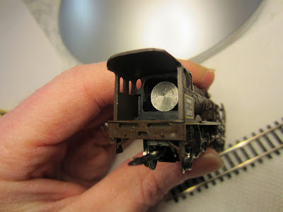
Now this gets me to wondering just what the French engineer and fireman were looking at in those days or nights. My cynical conclusion was probably not too much. Maybe this engine was intended to run clandestine excursions in cover of the night or darkness. But I suspect that field of forward vision in one of the smoking beasts at full steam was not very good. At this point of the rebuild I still needed to add more black paint to the rear interior of the smokebox to hide the light channeling through the CA glue and brass tube recesses. That since has been completed.

Once I was assured through fitting that the smokebox cover would not hit the lightbulb and bracket, I then used two tiny drops of CA glue to secure the cover to the boiler front. Some might advise against this, but it was not fitting secure enough to be held in place on its own. 
And I did not want to lose that item. It needed to be secured. Besides, the light bulb was not made to be accessed from the front. One needs to remove the boiler from the chassis apron to get to its mechanics.

By this point I had also attached the cleaned air tanks to the upper boiler shell. 
I used CA glue very cautiously. And once secure I placed small dabs inside the shell where the pins sit within the shell. By comparison to other similar vintage locomotives, I realize I may have inverted them. But it seemed that was the only way the tabs protruding from the tank bottoms fit within the holes on top of the boiler. Now that is a testament to futility. But ‘she is as she is’. I thought I had researched that well enough, but surely not. And I can only guess what picture I used for that final check to secure them. At least they are straight. And it is too late now; I will not attempt to reverse that move.  

Next it was time to get the weight rod assembly installed. 
Recall that the locomotive shell itself does not house the motor (or the ‘zamac’ thankfully). However, that renders it quite light in weight. And if things are out of alignment, I envision, and there are some reports, that the finely working tender driven motor at full steam will push that light engine shell right up and off the narrow track around a bend. Like a crab, moving crab-legged with legs scurrying sideways beneath the water. After all that careful work, if it hits the concrete floor you now have a true static display with plenty of spare parts for another. Fortunately it seems a rare occasion to have a good tender and locomotive combination. So if you are lucky it will either work correctly or not at all. All or none.

From all the prior work it was apparent the steel rod fit too snuggly within the boiler shell. It needed clearance. I filed the edges and top corners of the rod and screw that holds the headlight bulb contact blade. 
The small clip at the lower right of the picture is screwed to the bottom of the weight rod once it is positioned inside the boiler. That spring clip carries power from the rear of the chassis and drive wheels up through the weight rod forward to the bulb base through the fine metal spring blade that contacts the bulb base center post. Here is a picture from earlier in the build that shows the narrow confines within which this all operates. 

I also filed the inside of the boiler shell with a fine rat tail file. With time the rod was free to move inside. 
As I noted earlier, after careful fitting, I had secured the front smokebox cover to the boiler shell. So the weight rod could no longer enter from the front of the boiler. But the rear of the shell in the cab has another opening that is covered by the coal bin doors. I will touch on that part of the rebuild a little later. That opening allows access of the weight rod and its workings from the back end of the locomotive boiler shell.  

It was also necessary to make some allowance on the interior recess of the bottom boiler to accept the slightly larger lightbulb post base solder points. 
I used a small file for that work...

These pictures show the nearly completed locomotive:


The front left baffle or side smoke shield has not yet been attached. The latter picture shows the small size of this locomotive. With very careful application (via a toothpick tip) I used CA glue to attach the left front baffle or side shield. 
Note that the rear protrusions from the baffle side shields clip over two pins on the boiler sides. This raised recess on the right front baffle is evident in the left center of this picture. 
These are not glued. But rather press fit and ‘hold’ the boiler front within the shields.  

The picture above also shows the freshly painted front boiler cover. I realize it is still a little rough. But I have not yet decided how much to refine that. And there is still the question of whether or how I might add the Chapelon Herald that sat front and center on that cover. Sadly, that was turned to drilled plastic dust many years ago. The right front buffer (or bumper) still needs to be attached. It has survived and at this stage of the rebuild currently lives inside a plastic medicine bottle inside a candy box lid, inside a cigar box. (Ok, ok I confess. At this point I am reminded of Phil Hartmann, as the Anal Retentive Carpenter or preparing  a Thanksgiving dinner as the Anal Retentive Chef on early Saturday Night Live (SNL) skits. If you have not seen those, give it a shot. I still recall them as some of the funniest of those days. But I have learned it is best not to lose some of these small detail pieces. They are quite difficult to find or reproduce.)

With some  careful use of CA glue, I reattached the front buffer or bumper. 
If you look closely at the bottom of the re-installed front right buffer, it is apparent that the gloss white paint was missed on the lower edge from the factory. Careful application of gloss white Testers enamel with a 3O brush corrected the problem.  

Next I set about to ensure the boiler coal cover doors fit a little bit tighter. I mentioned earlier in the story that the boiler weight rod slides inside the boiler shell. When assembled from the factory I suspect it had the option of either end. But the front smokebox cover was quite loose in fitting. So I lightly glue it. This left the reverse end of the boiler shell to allow removal if need be of the weight rod. 

I carefully placed some cyanoacrylate glue on the left edge of the boiler door recess inside the cab. I did not set the doors in when wet. Instead, I allowed the glue to dry fully. I wanted to create a slightly narrower channel to receive the rear cab inside boiler cover doors. I then fit the doors and carefully scraped any dried excess glue to allow the doors to sit tight. 


Here are a few pictures showing the completed locomotive rebuild....


Here is a shot of the final locomotive with lights ablaze.   

These photos show the completed locomotive and tender.  


That concludes the journey of rebuilding one (of I anticipate thousands) of these vintage Italian Rivarossi N scale locomotives. It has been a challenging and a rewarding adventure. I have met several new friends, gained new knowledge and a new skill (although my wife might not necessarily agree). It also reminds me of days of my childhood, watching my father toil away at some of these fine little machines. Adjusting, lubricating and getting them to a better place. And that is a heart warming memory. Sometimes with dry eyes, sometimes not.  I now realize that many times he was working on these late into the evening while my brother and I were likely sleeping.

For reference here is a shot of this particular locomotive as she was found.  

Perhaps this particular French SNCF 231 Chapelon (4-6-2) might get to go to the prom after all.

Until we might meet again I wish you all well.

TJZ
Completed 4/26/2015
 -----------------------
Terry - thank you so much for sharing this terrific story and impressive restoration effort on a beautiful locomotive! Well done and 'le felicitazioni'!  - Jerry/Quinntopia