1.29.2011

Control Panel Progress (TCO!)

 A quick post to put some closure on a huge project that has taken up most of my modeling time in the past 6 weeks (and given the extra time during the holidays and winter season, that is a LOT of modeling time!) and that is the near completion of my "TCO" / Control Panel!

I've needed a control panel for some time...you just get to a certain place where the number of turnouts / points is so great that you can no longer use the readily available options from the manufacturers (e.g. Kato's 'big blue switch' etc...).

This is actually my second one...I completed a much smaller version of this for the "Green Line" a while ago.  I was able to use that smaller version to improve some of the things that I would need for this considerably larger and more complicated panel!
Once I finally figured out the final track plan for "version 4" of Quinntopia, I created a schematic control panel illustration (using Microsoft Visio, but virtually any drawing program will do) and then gave the file to a local printer who was able to provide me with a 'professional' looking control panel.

Then drill holes and -this is the laborious part-add all the wires!

Above the control panel I also have indications of the power status to each of my four 'blocks' (I decided at this point to set up my layout so that its composed of 5 independent power blocks so that if someday I need to upgrade my DCC power to a 'booster" system it will only mean changing a few screws) which are also each independently routed through  "OnGuard! OG-CB" circuit breakers (which now means a 'short' or derailment on one line will only stop power on that line and not all of them, even though I am still using one transformer/one DCC controller for the whole layout).

The "On Guard! OG-CB" circuit breaker boards (photo on right), also have LED output inidicator solder points, so the 'status board' portion of the control panel shows a blue led for power to each of the blocks, or will show a red LED if there's a short somewhere in that block.  Really nice to have this set up....with a layout getting as large as this, searching all of the track for some short can be a real pain!
 
Here's a little bit of a closeup shot of the main panel.   The lines are color coded to their respective 'blocks' (red line, blue line, and gray for the yard block; the LED turnout indiactors for the points will indicated 'green' for the points aligned for straight travel through the points, or red if its diverging.  The orange LED's are for the SPST isolated rails in the yard...again, not wanting to consume electricity with a fully lighted passenger train in the terminal, I can now just turn that tack off!
And here are some earlier shots of the progress....I started off thinking I might use the European style terminal strips for connecting my toggles at the control panel to the lines that run out to the turnouts, but I found this to be less than reliable so i ultimately abandoned using these strip terminals and soldered all the connections.  A much better solution!

Given the size of this control panel, there were very few options for where to place it.  Ultimately, I ended up putting it on the wall.  While this wasn't my first choice, it actually turned out to be a great one as the LED indicators are visible from virtually anywhere in my train room (which is in my garage if you didn't know!).  You can see it in the back ground below (the door to this walled off section of my garage is just to the right of the control panel).

This shot also gives a pretty good view of the 'Version 4' expansion...and the amount of work left to be done!
There's still six more toggles that needed to be added, and I need to add three more isolated track sections (two for the engine shed, and one for the main line siding). 

For the most part...its done! Its wired, its functional, and I can get on to some of the more fun aspects of the layout!

1.25.2011

N Scale Furniture from Luetke Modelbahn

Last month in my series on "Interior Modelling" I bemoaned the fact that there were virtually no furniture options for interior decoration of N Scale buildings.   Fortunately, I was incorrect!  Magnus of Tågomera posted a link in the comments for a firm in Germany called Luetke Modelbahn which not only produces N Scale furniture, but a nice selection of unique urban and other structures!  As a Christmas present (to myself!) I ordered each of the furniture options available from Luetke.

They offer four sets of furniture; two different sets for store interiors, a restaurant interior set, and a large (and the most expensive) office furniture set.
The office set comes with five separate sheets of furniture. molded in either white or a graphite gray. You get quite a few large storage cabinets, some mid-rise cabinets (credenzas?), plenty of conference tables, sitting chairs/couches (single, double, and triple wide?), two-pedestal desks (my favorite), and plenty of chairs.
The furniture is, thankfully, built to a fairly sturdy specification and cutting apart the pieces does not seem to be one of those exercises where a tedious exercise is not made more so from the fear of destruction!  Yes, there will be a fair amount of cutting and sanding with this furniture!
Hows' it all look?  Pretty fab in my opinion!  Of course, the below are unpainted, but a splash of some paint, and maybe a 'wash' or two, and we're in business (in N Scale!)!  Again, the sturdiness of the chairs is evident in the below photo.  Yeah, they would be pretty heavy duty in 'real life' but at 1:160 scale, I don't mind at all.
In retrospect, I do regret using my (cheap) Tomix features as models for this furniture....they do look a bit like creatures from a melted-face, zombie extravaganza more than real people, but the Priesser figures are still boxed up until all the layout vacuuming work is complete.
In total, theirs about 257 pieces with the office set, that works to a per piece price of $0.20, which really is a pretty good value considering that the Model Power park benches cost about $1.00 per piece!  Considering the amount of time it takes to build furniture from scratch, this is a good investment for me so that I can spend more time decorating and building structures, rather than searching for pieces to fit inside!

Alright...I can't waste any more time blogging right now, I have about a million little chairs to sand and paint (at last!).  Thank you Luetke!

1.23.2011

Minitrix Turnouts / Switch / Points

I've long sang the praises of the Kato Unitrack system (and many others who use it also agree as to its huge benefits and advantages) so this post and its topic should take nothing away from that praise.  Essentially, I need some turnouts (points, switches, etc...) for my freight and passenger terminal that required physical capabilities beyond what Kato's #4 turnout (or #6) could provide.

I considered Tomix, as that track system is equally well respected, but as this track is meant for yards, I didn't want to deal with the pre-ballasted track.   I also considered Atlas, as their track system is plentiful, cheap, and ubiquitous here in the States.

However, I already had some of the Minitrix track from a starter set, and had been using two of their switches in my industrial spur.  There is something about their track that is appealing just in the 'feel' of it.  I don't know if its the weight, or the solid feeling you have when you connect their track together, but I felt good about going with Minitrix.  However, I 
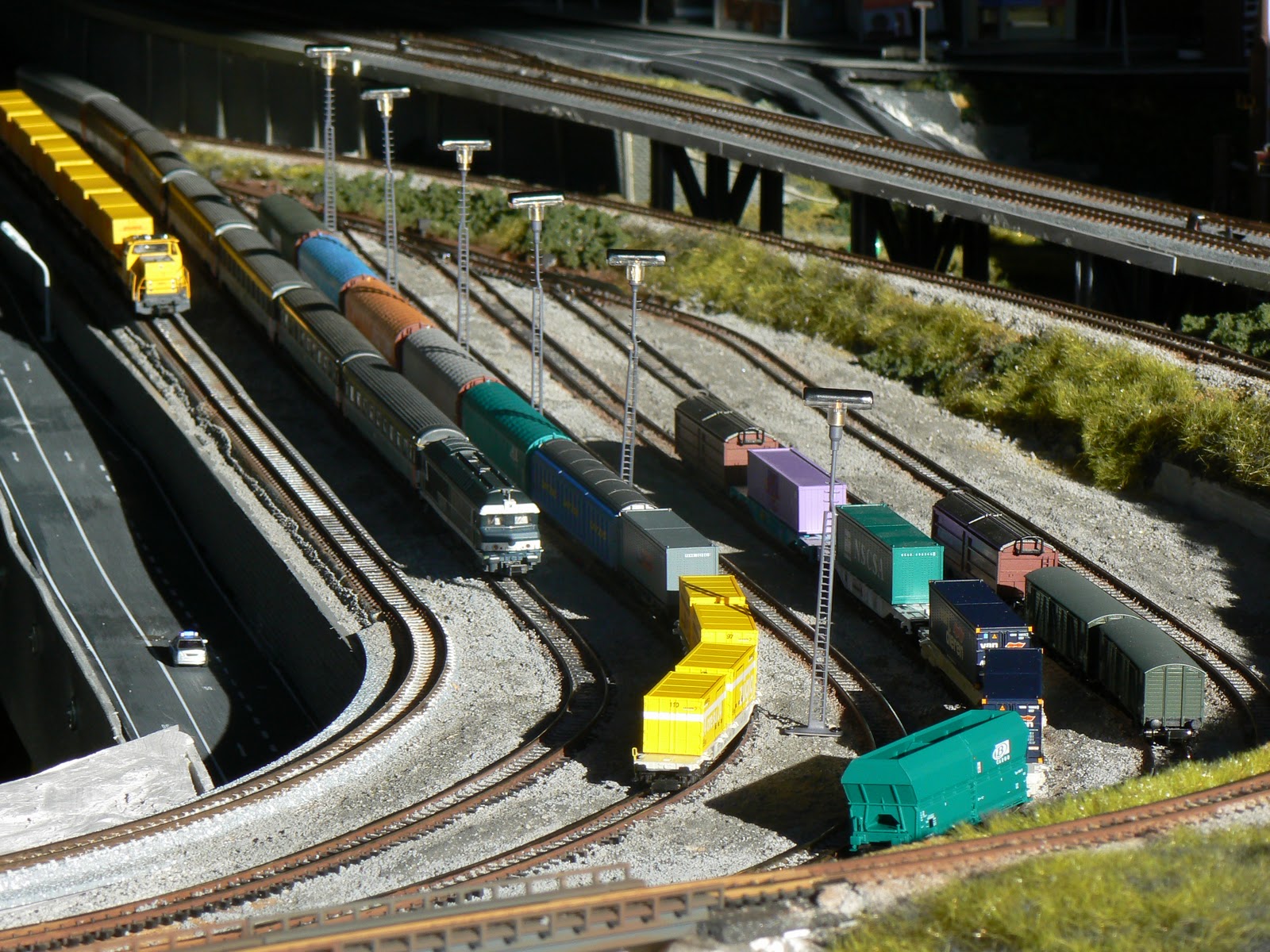
did use plenty of Atlas Flex Track (and for one curved turnout I even used a Tomix switch) so this is not a complete utilization of Minitrix.  Although it is rather unorthodox as most people either aren't aware that you can mix some track, or they expect significant problems with using track from different brands.  Given that Atlas and Minitrix are both the same height, and that they use code 80 rail the same as Kato, Tomix, and Fleischmann, it all seems to work pretty well together (detailed specs for virtually all N scale track is provided here).  Below is a photo of the yard area with the Minitrix turnouts and Atlas flex track being put together....
The other thing I liked about Minitrix was the way they allow you to connect their turnout motors to the turnout so that the turnout motor would sit flush with the tops of the ties (or sleepers).  Not only did I think this would clearly be more aesthetically pleasing than having the motor being exposed, but its also a far simpler solution than more complicated 'under the table' options.  The photo below shows the traditional motor attachment on the left, and the inverted attachment on the right.
The trick with having the turnout motors sit below the surface of the rails is that you simply attach (using some very straight forward metal tabs that insert into slots in the side of the turnout itself) the motor 'upside down'.   You're also going to have to 'reverse' the type of machine you use...i.e. use a 'left motor' for a 'right turnout' if your going to go this route!
As the now inverted switch machine sits slightly below the surface, you'll need to cut an opening for the switch machine to sit in.  For this, you can just trace the outline of your switch machine...in something like a cork under-layment the job is really easy.  If you're track sits on plywood, well, its a bit more trouble!
With the opening complete, you'll need to drill holes for the turnout motor, but really all that's necessary now is to put the turnouut with its motor in place.
 
When complete, the motor sits almost-but not quite- flush to the 'surface'.   Not as elegant as the 'hidden in the ballast' solution of the Kato or Tomix brands, but a decent approach!
As Kato's switches are single coil, I found that my next question was how to configure the switches to be remotely operated.  I'm not quite prepared to convert my switches to DCC control yet....for whatever reason I like the look and feel of a nice 'control panel' with all its toggles, etc....

While I found a really good solution for operating my Kato switches (using a design developed by George Stilwell ("easyBCD" which he shares on the Yahoo! Kato Unitrack group), my searches of the internet found no comparable design for the two-coil design (Okay, that's not precisely true...I did find several, but I understood little or it looked a lot more complicated than I wanted to pursue).  What I did find was actually much easier, and that was the 751d turnout controller designed and created by Ken Stapleton.  At $8.00 apiece (fully assembled) these are actually really well priced (considering the ancient Atlas Slide switch goes for about $4.00 and the Kato 'big blue' switch at around $7.00) and are really a value when you consider the features that Ken put into these machines!   Ken was also very available over email to answer some of my questions about using these controls with Minitrix turnouts (to my knowledge, they hadn't been used with Minitrix motors).
The biggest drawback I've found with these switches is the physical interaction between the motor / solenoid mechanism and the actual switch itself.  Essentially the red 'lever' that throws the points sits in a small gap withing the motor mechanism.  While this is fairly straightforward, its not 100% reliable.  Several times I will throw the switch at the control panel (and hear the appropriate 'snap' sound) only to find that the red level skipped out of the slot in the motor.  Sometimes this has to do with the alignment of the motor on the switch machines, which can be addressed by propping it so that the contact is more certain each time.
Bottom line is that these turnouts are not as reliable as the Kato turnouts.  I'll give Kato a 95% reliability rating, while these Minitrix switches get an 80%.  However, one advantage is the ease of replacing motors with the Minitrix, which is not at all a feasible option at all withe Kato!  In terms of cost....well, it sort of depends on the latest exchange rates!   The polarized frog turnouts I went with (15 degrees) are not cheap...in fact, they are slightly more expensive than a Kato #6 turnout....and that's before you paid another $15 for the motor mechanism ( I have questioned my judgment when the cost started adding up with these!).

So there you go....if you want a turnout alternative that is more expensive and not as reliable as the Kato, and will not be readily available at your local hobby shop (unless you live in Europe I imagine!) you should consider Minitrix as one of you options!

(See? I'm still praising Unitrack...even when I'm not!)

1.16.2011

Bus Wiring (Demystified!)

I may be the dumbest model railroader around.  Or I may just be a normal guy who doesn't quite understand the language of electronics that I'm often confronted with in this hobby.   Thank goodness for the internet where I can find people to explain and clarify concepts that I don't quite understand!

One of those concepts, as you can probably predict from the title of this post, was the topic of "bus wiring".   For a long time I really didn't understand what this was or how it would benefit me.   I recall reading some manufacturers DCC instructions and coming across explanations like "Connect the red wire to the main track bus" etc....  Utterly confusing to me.

For the first several years of my layout (fully DCC), I was, in fact, able to get by just fine without really having to worry about this.   My wiring 'system' (if it can be called that) was to essentially use the Kato 3-way connectors in sort of a 'hub and spoke' arrangement to distribute power around my layout.   Imagine the below with three more 3-way connectors branching off to power the track.  This was my system and, for the most part, it worked.
For the most part ....because I was having some problems which I now know were due to my above wiring scheme.  I have three separate lines on my layout, all essentially concentric ovals that traverse the diameter of my rectangular layout (before my latest expansion anyway).  This gives these lines a total running length of about 15 feet or so.  The exception to this is the 'Blue Line' which uses gradients to double under itself and is effectively twice as long as the others....about 30 feet.   On this line I had been noticing some peculiar behavior with my locomotives....mainly a lack of responsiveness to commands.   I initially attributed this to dirty track, crappy Trix Mobile Station, poor decoder connection, or a variety of any number of things that could be potential causes.

As I started my expansion....and looked to add another 15 to 20 feet of running length to my main line, I started to question my 'lazy Unitrack' wiring scheme.  Fortunately, a post on the JNS forum was able to explain, demystify, and encourage me to do the 'right thing' and move to a real 'wire bus' (after first reading other members postings on what exactly it was!).

As I discovered, "Bus Wiring" has nothing to do with buses, trams, trolleys, etc.... it really is (as far as I understand anyway) the simple fact of laying down a 'main' power supply around the layout and then 'tapping' into this 'main' power line for your track feeders.  The below illustration is how I ultimately moved to a bus wired layout from the above 'lazy Unitrack' version:

For each of my four 'power districts' (the original 3 lines mentioned above, plus a new, separate section for all of the new yard tracks), I picked up 14 or 16 gauge stranded wire from the local automotive stores where I was also able to locate some handy 'suitcase connectors' which attach to the 'bus lines' and feature companion connectors that get crimped on to the 20-22 gauge 'feeder lines' that go to the track.
For installation, I usually tried to keep the length of my feeders about the same length as the average Kato power feeder.  I tried to do this consistently (for reasons that I'll try and explain below).  The below photo shows a Kato connector that is drastically shortened and I don't use on my layout, but it illustrates how you could continue to use the Kato connectors with this system if you choose to do so.
THE RESULT:
These electrically inclined people really do know what they are talking about!  My issues, particularly on the "Blue Line", with poor responding locomotives have disappeared!  The reason for this (covered in much more detail on the JNS Forum) is that on my longer routes, the actual DCC signal reaches the track at different times ---- granted this is in milliseconds---but it still (I believe) is enough of a delay for the decoder to get some sort of garbled signal from the DCC controller. 

Note that this 'responsiveness' issue I had on the "Blue Line" was not a problem on my shorter routes (I elected to upgrade them to a 'wire bus' anyway) so I do think this problem probably only comes up when you reach a certain threshold in terms of route length.  For small ovals, this will probably not be a problem, but as I experienced as I continued to add length, it was time for a better approach than the simple approach I was initially able to take.

1.03.2011

Locomotive Roster: SNCB Series 59; Roco 2156

I picked up this older Roco model last Summer after my trip to Europe.  I liked the rarity of this model as it pertains to European N Scale, and I also like the fact that Belgium now gets a little representation on the layout!  This Roco model of the Series 59 from the SNCB / NMBS also has more interesting history as the prime mover of the original locomotive was a Baldwin 608A, which makes it a distant cousin of the famous Baldwin RF-16 "Sharknose" diesels
My personal challenge with this locomotive was converting it to DCC.  So it sat in its box for the past 6 months or so while I went back and forth on my potential ability to install a decoder, and worked on the layout.   Having successfully installed a decoder into my new Kato Sunrise Express motor car (great post on the JNS Forum for this) yesterday, I was feeling confident enough to take a crack at this locomotive. I tried several searches to see if there were any recorded experiences of this engine's conversion to DCC on the internet (in any language!), but I couldn't find any, so I knew I was on my own!

First, I'm starting to get a LOT more comfortable with the basics of decoder installation.  Essentially the main thing with a decoder install is that you need to install the decoder between the rail pickups and the motors (and ensure the ONLY contact between the motor and the electrical pickups is through the decoder wires!).  Everything else is just details.

With that in mind, I studied the locomotive for awhile to get a sense for how I could try and accomplish a decoder install on this engine.  The most noticeably thing about the motor and interior is there is a circuit board with four wire leads which, by examining, I determined were all power supply from the rails.  Knowing that these are my electrical pickup leads from the rails, I looked for the contact between these and the motor.  Ah hah!  Two brass strips extend down from the decoder to two prongs which come out of the closed motor casing.  All the other circuitry on the circuit board appeared to me to be for enabling the light bulbs.
With my basic rule in mind about decoder installation - and with the intention to replace the existing bulbs with LED's wired to the decoder - I felt confident enough about cutting the wires and removing the old circuit board.  I also cut a strip of styrene to replace the circuit board and to provide a platform for attaching the decoder and securing the wiring.
My first step for installing the decoder was to cut the orange and gray leads from the Digitrax DZ125 I was using (cheap, although not the most reliable) tin the ends, and then solder to the to motor prongs.  This was an easy step as the 'prongs' are easy to access and with both the prongs and ends of the wires tinned, putting a small amount of heat to the prongs was enough to make a good contact.
Next I soldered the black and red wires to both of the supply lead wires I cut from the circuit board.   The black wire from the decoder was soldered to the the two 'supply' leads (from the bogies/trucks) on the same side as I attached the gray wire to the motor.  The same was done with the red wire and the two supply leads on the side of the motor where I soldered the orange wire to the motor prong.
The moment of truth....I put the engine on the programming track to see if my approach was correct...and Wallah! It worked!  With the knowledge that I had all the wires in the right places and a correctly functioning installation, I then proceeded to add LED's for each side of the engine.   The LED's needed 680 ohm resistors on the white and yellow wires coming from the decoder, so these resistors were added.  Again, another test to see if the LED's were attached correctly...more success!  Then the process of applying "liquid electrical tape" to all the metal connections, and double sided tape to secure the decoder to the plastic strip, and kapton tape to keep everything in its place.
The real moment of truth...putting it on the layout and attempting to address it and check to see that all of the functions work as they are supposed to....SUCCESS!
This was a great achievement for me.  While it wasn't my first hard-wired decoder install, it was the first one where there was no information for this model available to guide me through the steps (and to reassure me that the steps I were taking would work!).  Hopefully this post will help to either be an encouragement to other 'non-electrical' folks like myself, or some specific help to guide you through a similar loco conversion!

1.01.2011

Freight Yard Progress!

A very Happy New Year to all!  I feel good about 2011....for us N Scalers, I think its a good time, with all the European companies finally having settled various financial issues over the past several years (Marklin/Minitrix, Roco/Fleischmann, Kibri/Viessmann), new offerings in N from Lilliput and Piko, and some excellent Trams from Kato, there is lot's of interesting and exciting things happening....and finally let's hope that our worldwide recession is a memory this year and we can all move on to more prosperous times!

2010 was really a year of major expansion and construction for Quinntopia....it started last year with an ambitious project to redo the layout to expand my 'downtown' and add a tram line, create an interesting viaduct scene, and finally do something about my freight yard.   Last summer, my construction work continued with an even more ambitious expansion of the layout outside of its previous dimensions! This included grades, bridges, painting my rails a good rust color, a new passenger terminal and more.  In between all of this has, of course, been several new buildings built and lit.

Behind the scenes, I've also been upgrading all of my electrical work....I now have a 14 gauge wire bus for each of my four 'blocks', which I've noticed has increased the responsiveness of my locomotives where previously they would seem to ignore the commands!  This expansion (especially with all of the yards) required some serious (for me) thinking about how to control all of the switches in a simple, efficient way, so I've been spending a lot of time thinking about how my "TCO" ("tableau de commande optique", or "Control Panel" as we might say in English [Thanks Pascal!]!  I just like the sound of "TCO" better than control panel!) will look and planning to put it all together.

The good news is that a lot of the above is accomplished, and the layout is now - for the most part - ready for trains to be run again!  Its really amazing to think that for the past year, most of my trains (and new ones I have acquired) have had little or no running time at all!  I'm hopeful that this has changed!

The above photo (and those below) show the nearly completed freight yard (nothing is ever really 'finished' I find!).

Below is my SNCF CC72000...now one of my favorites given its aggressive looks, classic 'broken nose' and dynamic paint scheme.   The roadway in the foreground was added to give some depth to the yard...and to act as a 'safety mechanism' (or 'anxiety remover'!) to prevent trains from free-falling to the floor!
Another new acquisition on the 'main' passing the freight yard is this beautiful looking Nederlandse Spoorwegen (or "NS" as its commonly referred to in Europe-fellow North Americans will notice this is not the other "NS": Norfolk Southern!)
Stepping back a bit (as my 'train room' sits in a garage, one of the few advantages is to open up the door for some natural light! Although its a very cold 25 Fahrenheit today!) shows the layout (the expansion with the new passenger terminal and running room is out of the photo on the left)
Stepping back a bit (as my 'train room' sits in a garage, one of the few advantages is to open up the door for some natural light! Although its a very cold 25 Fahrenheit today!) shows the layout (the expansion with the new passenger terminal and running room is out of the photo on the left) with the viaduct in the foreground, yard on the left side, and 'downtown' in the back in the shadows.

Today's project is wiring and assembling the "TCO"....as you can see, a lot of 'speghetti' at the moment....but soon to be organized and arranged in proper order!
Thanks for reading and, again, Happy New Year to all!