11.11.2012

Video Montage #2 for 2012


As I try to optimize my hard drive to help my aging iMac out, I found I had a lot of video not yet used or shown, so I decided to create another 'montage' video of the layout.

Very hard to find any sort of theme in this video, mostly just some favorite layout shots.   Some of the shots go back several months before the station area or various areas of scenery were complete.

Also, have to give a huge plug for the excellent music from a band called "Methodic Doubt Music".  The track title is "Hero's Blood".  They seem to specialize in a genre of music called 'trailer music' which - not surprisingly - works very well for short little train videos!

Anyway, I hope you enjoy!

11.04.2012

Locomotive Roster: Arnold 2471; SNCF BB 25201

Last Christmas I was happy to receive this dashing looking locomotive from the SNCF; an Arnold 2471  class BB 25200 number 25201.   I had spotted one of these a while back and there were three things that I really liked about it:

  • Despite the fact that its an older production model, details and graphics are very nice
  • I liked the white/orange/black paint scheme
  • I love the curved cab window styling on these French electrics!

The Arnold Model:
The Arnold model I have (#2471) was cataloged sometime between 1989 and 1994 and according to the database at Spurweite-N.  Given the time frame, this is obviously an analog model and will require conversion to operate on a DCC layout like mine!  Spurweite-N also lists a another version of this model (#82471) that allegedly was sold with a digital decoder installed. I find this fairly surprising (the available data for this supposedly digital version are the sames as my analog version.  While I don't dispute there was something like DCC around during the early 1990's I am a bit skeptical that Arnold would have sold an already digitized version.  It might be that the catalog dates for the digital version are incorrect and they reflect the early 2000's and not the '90's, which would be more believable).

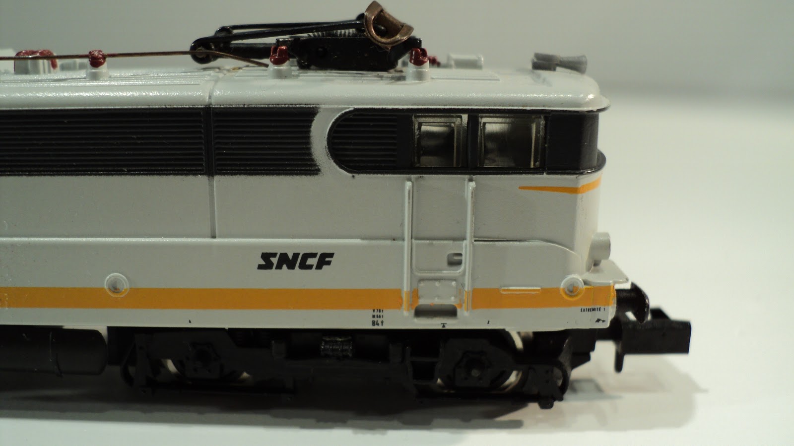
The below photo shows the fairly impressive detail (in my opinion) for a model produced in the early '90's!
Don't confuse Arnold's model of the BB 25200 with their much earlier model of another and slightly similar BB 9200, which comes from the 1970's era and represents what I think would be considered rather crude detail, low quality graphics, and rudimentary mechanisms.  I'm basing this off of photographic comparisons which make the visual comparison fairly obvious, and I would expect the mechanical mechanisms to be fairly crude and representative of the first generation of N Scale models.

The Prototype:
The BB 25200 class was, and is, a bi-current locomotive able to operate on France's two main standards for electrical locomotives (1.5kv DC and 24kv AC - which is a legacy of France's pre-nationlization private railway standards before 1938).

These locomotives were produced for the SNCF between 1965 and 1975 and, from what I can tell, would pull both passenger and freight trains as necessary.

This electric locomotive, which I tend to think of as a 'box cab' given my American orientation, has some of the distinctive styling that I love about the SNCF - mainly those super-cool, styling curved window elements.  It reminds me of the sort of decorative flourishes' that were applied to cars, buildings, and all sorts of other engineered elements back in the 'old days'.
I'm also intrigued by the livery (another reason I enjoy the SNCF so much....despite being a state-run railway, the diversity of different liveries is pretty amazing, and most of them are pretty amazing and attractive!) which is described as the "Le Mans" livery.  I can't tell if Arnold did a good job or replicating this livery, the few photos I've found of prototypes in this scheme seem close, but something is not quite right.  I'm not too crazy about the precise shade, and being somewhat ignorant of the prototype helps to appreciate the model for what it is.  It is interesting, I can't tell if the base color is white, or more of a light grey? If it's light grey, then its very reminiscent of the current 'concrete' scheme that is frequently seen (grey with organge stripes).  So perhaps this livery was something of a predeccesor?

According to Wikipedia, many of these locomotives operated (and still do?) in the Rhone-Alpes region of France, which borders Switzerland and Italy, where the largest city is Lyon.
Perhaps not surprisingly, these locomotives have put in their time and many of them are being replaced by newer EMU's, Prima's and so forth.  Amazingly to me is that the last production of these was in 1975 and here, 35 years later, even a few are still in operation!


Converting to DCC:
As I mentioned above, despite the good quality of the casting and printing, this locomotive was produced before the idea of digital really took hold, so converting to DCC is somthing you'll have to do yourself (or pay someone, or find a friend!).

I was able to accomplish this using a tutorial on the French N Scale Forum, but as the original instructions are in French, I decide I would pass on the good knowledge I learned from this site and member "Oliv CTR" (Merci!) and contribute my own photos of the process.

One of the first things I learned from the French forum, is that there is not a lot of room for the decoder, so the thinnest decoder you can find is advised.  I used an Ulenbrock 73400 which is only 2.4mm thick and will fit nicely within the enclosure.
Removing the body is a little unusual, as you have to remove a screw from the bottom of the chassis, which releases the two plastic tank sections which then allow you to remove the shell.  Trying the remove the shell without remove the screw will probably wreck your locomotive.
Once the shell is off, you will see the PCB board, which is where most of soldering and digitizing operation will take place.  Remove the two screws which hold the PCB board to the chassis to work on the decoder install.  Once those two screws are removed, you can slide the PCB board off the motor contacts and metal base.
 Again, space is tight, so in order to add the decoder, something must be removed.  Following the instructions from 
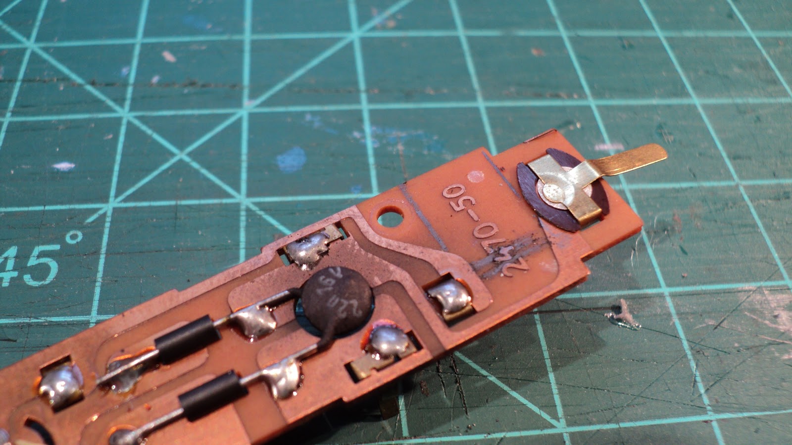
"Oliv CTR" on the N Forum, I chose the same relatively 'blank' area as he did.  I don't really know if there are other options, but this location works well.  In the below photo, you can see some pencil lines where I planned my cuts.
A razor saw is a really nice tool for making sharp cuts in the PCB board.  I scored the bottom area of the cut-out area with a knife and was able to snap away the unneeded section of PCB.
One thing I've never done before (at least in the very few DCC conversions I've done myself) is to shorten up the wires prior to install.  My typical inclination is to assume that there will be enough room to hide excess wires away after everything is installed, plus I want the safety margin of extra wire...just in case!   Well with this loco there is no extra space, so I decided to shorten my wires before installation to get as little slack in the final install as possible!
The below photo shows the PCB board with the cut-out section for the decoder, as well as the PCB copper strip connection you will need to severe to the light and the diodes and capacitors that need to be removed.
With everything  but the white wire soldered, below is where the various wires get soldered.  While it may seem somewhat complex, being able to do all your wiring right on the PCB itself make this a fairly easy decoder install.
I chose not to replace the old-fashioned incandescent bulbs with LED's.  If you wanted to do that you would also need to find space for the resistors as well.

Putting the loco on the track, I'm always a little relieved that anything works that I have put a soldering iron to!  She runs nicely, if a bit noisely, which I attribute to a 20+ year old mechanism!

On the down side, the bulbs are extremely dim and the connections could probably use some cleaning as the light doesn't stay on consistently when in DCC mode.  The lights only work in one direction as well...hmmm....something to consider.

11.02.2012

Luetke Office City Tower Build Step # 10

STEP 10

Wrapping everything up in this final post on the office tower!  As I mentioned in the last post, everything was ready to add the upper 11 story section to the bottom 15 story section.  A couple of things need to happen in this step:
  • Do several test fits to ensure that the top section will sit vertical on the bottom section (indeed; I needed to add a bit of shimming material to address a small 'tilt')
  • Solder connections from the brass rods between each section (insulate, etc...)
  • Ensure that the windows are aligned between the two sections.
And below is the first look of the 99% complete structure on my workbench!
 I was anxious to get this structure onto the layout and fill this long awaited spot:
A 'daytime view shows the surrounding area a bit better: 

But I think it looks much better at 'nighttime':
There's a small open space next to the Office Tower that I filled with one of my very first building modification attempts.  This little Tomytec structure has been sitting in storage waiting to find an opportunity to get back onto the layout for a while now, and I just sort of felt a small, older structure might fit the area well.
 While I'm somewhat unhappy with how some of the windows/exterior wall sections turned out.  They are not too noticeably, so I have to look past what are obvious flaws to me and try to appreciate the building overall, which I think turned out okay. 

The interior lighting and accessorizing turned out really well.  The LED strips I used have the perfect luminosity and they feel like real office lights.  The desks and others pieces I added to the lit floors seem convincing enough from a distance.
The rooftop lounge is something I took some liberties with.  The original instructions indicate that this top of the building glass section actually contains two floors, but I decided to skip the additional floor and just go with really high ceilings in this lounge. 

I had another error with the small columns that go around the glass walls just on the inside of the lounge as one of them developed a lean after the roof and other pieces were already applied.  Its too much work (and might cause more damage) to try and fix it, so it'll be yet another flaw I'll have to try and ignore.
For the lounge interior, I did a couple of things.  I created some scratch-built lounge tables and chairs from styrene, painted and installed these, and added some customers.  I also attached some yellow (is there any other kind?) capton tape over the LED's to better distinguish the lounge from the office areas below.  And as you can see in the below photo, some art work for the walls:
And finally, for the surrounding area, the original base piece got cut back even more as it was still too large and wasn't working with the design of the block where I installed it.  I also added some foliage to add a touch of landscaping around the building.
That's it! 

Here is the complete list of the posts/steps for this building:
Step 0 (Preparations)

Luetke Office City Tower - Instructions

Luetke Modellbahn Office Tower Instructions

As promised, below are the instructions that I had to type into Microsoft Word to get into Google Translate to at least have some idea of how to go about building this structure! 

I'm posting them in German in case someone wants to paste these into a translation program for another language.  Please note that the transcription is not 100% precise and any errors are solely my fault and may (uh...will!) lead to very confusing and difficult to interpret language!

Below the 'original' German instructions are the translated instructions in English.  As you may have noticed in this series of posts, I tried to follow the sequence as much as possible, but soon found that I had to abandon the instructions and freelance a bit.  The below instructions may help those who prefer to follow Luetke's official version!


ORIGINAL GERMAN INSTRUCTIONS


1. Die beiliegende kurze Glasfassade mit Turen fur die eingangshalle wird an den senkrechten nuten leicht nach hinten geknickt so dass die runder form stuckwise vorgebogen wird. die knicke anpassen, dass ein gleichmassiger kreis entsteht.  Anschliessend die fassade in die Nut der bodenplatte einsetzen, beginnend mit der Wand zwischen den Drehtüren, und ebenfalls mit wenig Kleber befestigen. 
Eventuell die lange der fassade angleichen damit keine Uberlappung an der stossfuge entsteht.
Zur Montage der Drehturen werden die durchsichtigen Drehkreuzwände verschränkt zu einem Kreuz zusammengesteckt und verklebt.  Dieses Kreuz auf die Nuten der Trommeltürdecke kleben.  Ebenso die Halbschalen in die Nuten kleben.  Nun konnen die Drehturen eingesetzt werden. Zur Gestaltung der Eingangshalle muss nun die Animierung mit Figuren und Möbel statfinden.
2. Danach die schwarze Untersichtplatte Ea mit der kreis förmigen Nut auf die Fassade stecken unde fixieren. Die semicircle formigen Kernöffnungen mussen jetzt übereinander liegen.  Die acht 4mm starken stutzen werden nun von unten durch die Bodenplatte in die Untersichtplatte gesteckt und an der Bodenplatte verklebt.
3. Die weisse Bodenplatte Ec des 2.OG wird jetzt auf die Untersichtplate deckungsgleich gelegt unde leicht fixiert.  Auch hier mussen die Kernöffnungen ubereinander.
4. In die 4 Kerben der Bodenplatte werden jetzt senkrecht die Nutleisten Df geklebt und bis zur Aushartung senkrecht fixiert.
5. Stück für Stück werden jetzt die 11 Normalgeschossplatten Dd in die Nutleisten geklebt (Auch hier die Ausrichtung der Kernöffnungen und die senkrechte Ausrichtung der Nutleisten beachten so dass die geschossplatten nicht gegeneinander verdreht verklebt werden)
6. Als nachste Ebene klebt man nun die Untersicht Ed bundig auf die Nutleisten.  überstande der Nutleisten werden an der Oberseite gegebenefalls plangeschliffen.
7. Auf diese Flache klebt man nun, Nut nach oben, deckungsgleich die schwarze Dachterraseenplatte Eb.  (Ausrichtung der Kern offnung beachten)
8. In die beiden Kern offnungen schiebt man jetzt die geraden Kernwande Fb mit den Türöffnungen bis an die Unterkante der Bodenplatte ( leichtes seitliches Verschieben erleichtert das Durchstecken) An der Bodenplatte wird die Kernwand angeklebt.
 9. Im Dachbereich schiebt man nun die weisse Galerieplatte De über ie beiden Kernwande und klebt die inneren Zapfen in die zweitletzten Türöffnungen der Kernwande.
 10.  Die acht 1.5mm starken Stutzen klebt man jetzt in die Bohrungen der Dachterrasse Eb, richtet die Galerie horizontal aus und fixiert daran die Stutzen.
 11. Die Glassfassade der Dachgeschosse wird wie die Erdgeschossfassade an den senkrechten Nuten leicht geknickt bis ein gleichmassiger Ring entstanden ist. Dieser Ring wird jetzt in die Nut der Terrassenplatte Eb geklebt.
 12. Auf dieser Fassade wird der schwarze Dachkranze Db befestigt. Die Ausrichtung erfolgt durch die Kernwände.
 13. Die gerillten Kernwande Fa werden um einen Rundstab vor gebogen und von oben in die Kern offnungen geschoben.  Auch hierbei hilft es die Wandscheiben dabei seitlich zu verschieben.  An der Unterkante der Bodenplatte werden die Wände festgeklebt.
 14. Die Kern spante Df wird 1 mm unterhalb der Kernwandoberkanten in die Kernwande geklebt. Die Kreisform wird eventuell mit einem Gummiband fixiert bis der Kleber abgeluftet ist.
 15. Als Abschluss wird nun die Dachscheibe Dc mit der Ringnut über die Kernwände gestulpt und verklebt.
 16. Abschliessend warden die Tiefgaragenzufahrten jeweils mit der kurzen Brüstungswand Fd an der Innenkante, mit der langen Brüstungswand Fe an der Aussenkante versehen.  Verbunden warden diese Wände emit der Brüstung Fc.  Die Fahrstrassen jetzt leicht nach unten biegen und an den Unterkanten der Seitenwände verkleben.

ENGLISH TRANSLATION

1.     The accompanying short glass facade with doors for the entrance hall is on the vertical grooves bent slightly backwards so that the round shape stuckwise is prebent. Adjust the wrinkle that a bigger circle is created equal. Then the facade into the groove of the bottom plate attached, starting with the wall between the doors, and also with a little glue.

Any of the long facade align so that no overlap occurs at the joint.

To assemble the rotating doors, the transparent hub walls are put together through a cross and glued. The cross on the grooves of the drum door blanket stick. Also, the half shells stuck in the grooves. Now, the rotation can be used doors. To design the hall now has the animation statfinden with figures and furniture.

2.     Then the black soffit plate Ea with the circular groove put on the facade fix unde. The semicircle shaped core holes must now align. Clip the eight 4mm thick are now inserted from below through the base plate into the soffit plate and bonded to the bottom plate.

3.     Third The white bottom plate of the 2nd floor is now set Ec congruent to the soffit plate ande easily fixed. Again, the core holes must superimposed.

4.     4 notches in the bottom of the plate are now perpendicular Df the groove strips glued and fixed to the cure of vertically.

5.     Piece by piece, now the 11 normal Dd floor plates are stuck in the groove strips (Again, the orientation of the core holes and the vertical alignment of the groove strips note so that the floor plates are not glued turned against each other)

6.     Next level as you stick now the soffit Ed bundig the groove strips. over distances of the groove strips are ground flat on the top if given.

7.     In this area you stick now, groove up congruent the black roof Terra Lakes Eb. (Alignment of the core opening note)

8.     In the two core openings to push the now straight core walls Fb with the door openings up to the lower edge of the bottom plate (slight lateral displacement facilitates leadthrough) On the bottom plate is the core wall glued.

9.     The roof area is now pushes the white plate De gallery on he two core walls and the inner pins stuck in the second to last door openings of the core walls.

10.  The eight 1.5mm thick piece you stick now in the holes in the roof terrace Eb, directed horizontally from the gallery and it fixed the pipe.

11.  The glass facade of the top floor is like the ground floor facade is on the vertical grooves formed slightly creased to an equally massive ring. This ring is now stuck in the groove of the deck plate Eb.

12.  On this front, the black roof wreath Db is attached. The alignment is performed by the core walls.

13.  The grooved core walls Fa are bent around a rod before and pushed from above into the core openings. Again, it helps the shear walls thereby to laterally. At the lower edge of the base plate, the walls are glued.

14.  The core is glued joists Df 1 mm below the upper edges of the core wall into the core walls. The circular shape is fixed with a rubber band may be until the glue is abgeluftet.

15.  To conclude then, the roof panel is Dc with the annular groove turned up cuff on the core walls and glued.

16.  Finally, the garage driveways warden respectively with the short parapet wall Fd at the inner edge, with the long parapet wall Fe provided at the outer edge. Connected these emit the parapet walls warden Fc. The roads now driving down slightly bent and glued to the lower edges of the side walls


11.01.2012

Luetke Office City Tower Build Step # 9

STEP 9

While I would like to continue to follow the sequence of the official Luetke Modellbahn instructions, at Step 9 they've jumped ahead to some relatively minor details surround installing the poles that go into the lounge/gallery area at the top, and I've still got to try and figure out how to get these two large sections together.

When I complete this series, I'll post the entire German and Google-translated English version, but for now, I'm free-lancing.


In Step 8, we finally got to add the exterior walls (and some other stuff) so that we now have something resembles a building finally! I love this part! Up until now, its hard to tell what it is!


The Rooftop Lounge:

One of the cool features of this structure is the rooftop lounge and that somewhat iconic roof.  Unfortunately, you also need to get the glass walls to curve into a small groove on the floor section to make it all work. 

For adhesive, I used something different this time.  Its a glue from Faller called "Super Expert" and its really quite nice.  Its a slightly thick liquid that seems to adhere plastic articles really fast.  A lot easier and cleaner than other plastic cements, and doesn't get stuck to everything or cause fogging the way CA does.  I also like the needle point applicator the container comes with to get the glue exactly into the small grooves (note: the small diameter of the applicator will clog with dried glue, but I just use some thin 30 gauge wire to clear it out and its good as new).  Photo from Faller website.


The below photo illustrates this quick step (note the pre-drilled holes in these pieces for the brass rods that carry the electricity up through the structure):
This section is then applied onto the top of the floor sections (either the 11 story extension, or onto the 15 story base building, your call.  I placed the shorter 11 story section on top).  I painted the floor to create some contrast between the roof exterior and the interior area.  You can also see the brass rods now partially hidden behind the interior wall sections that form the elevator shafts, etc...

Connecting:

Now it comes down to 'connecting' the 15 story and 11 story structures to form our 'skyscraper'.  There are some interesting pieces remaining in this kit that haven't been used, and some confusing Anglo-Deutsch-Google-eese that I can't understand related to this pieces, so I just sort of played around with different configurations that seemed similar to photos in the instructions and what seemed to work from a structural perspective.

This could be wrong, but it seemed to work for me.

Included with the 11 story extension is a solid, cylindrical piece referred to as the "Technikfassade" that goes somewhere between the two sections.  I think mine is upside down, but it actually fit a lot better this way for me.  There's also a white rung (called the "Technikring") that I glued into this as well.  This "Technikfassde" piece was then attached to the bottom section (which is the 15 story section in my build).
 
You'll notice the holes in the below photo with wire leads coming from one of the brass rods poking through from the bottom.  This is the place to connect / solder the brass rods from the upper section to the below section.  I found it helpful to mark the brass rods with a red sharpie to ensure I kept the polarity correct while I attached everything.
One more thing, if you look at the above photo, at about the 3 o'clock position, you'll notice a small gap in the exterior wall.  Yes, it turns out something didn't work out correctly and the walls on this structure were a bit short.  I glued a flat black strip of styrene into the gap so that the very noticeable building underneath didn't show through.

Okay, next is putting it together and lighting it up! We're almost done!


For reference...
Here is Step 0 (Preparations)
Here is Step 1
Here is Step 2 
Here is Step 3
Here is Step 8