10.31.2012

Luetke Office City Tower Build Step # 8

STEP 8

Step 8.  Sort of.  You see at this point we're going to relying on a bit of creativity.  As I mentioned in my last post (Steps 4 through 7) there are no instructions with my kit on how to add the additional 11 story 'add-on' section to the main 16 story section.  

In Steps 4 through 7, I explained how I added each floor into the 4 grooved vertical strips, and then placed the 'roof' soffit piece on top.  Its the same process for the 16 and 11 story sections.


The instructions for Step 8 in my original instructions disuss how to start adding the top floor and interior walls, which we don't want to do just yet until we figure out how the original kit and the additional structure go together.


Nevertheless, here is the original German and English translated instructions for Step 8: 


German:
8. In die beiden Kern offnungen schiebt man jetzt die geraden Kernwande Fb mit den Türöffnungen bis an die Unterkante der Bodenplatte ( leichtes seitliches Verschieben erleichtert das Durchstecken) An der Bodenplatte wird die Kernwand angeklebt.

English:
In the two core openings to push the now straight core walls Fb with the door openings up to the lower edge of the bottom plate (slight lateral displacement facilitates leadthrough) On the bottom plate is the core wall glued

Instead of following those instructions, what I am going to do is:


  • Insert the 'center wall' sections into both the 11 and 16 story sections
  • Apply the clear window plastic
  • Apply the exterior walls

Adding the Interior Walls:


There are two long, flat strips with door-sized cut outs for each 16 and 11 story section.  These should be inserted first.  These are pushed down through the top semi-circle all the way down each floor until they extend into the holes in the bottom section (they should be flush on the bottom and - eventually - the top [whereever that is, at this point its not clear given we're going to add a section to the top of this])


In the photo below I have the above 2 flat, smooth sections installed which are behind the 'corrugated' sections (in blue) which get inserted after you have the flat sections in.  I added some notes to the below photo which I hope help.  IMPORTANT - This photo was taken after the clear, plastic 'windows' were applied...you DO NOT want to insert these interior walls after you apply the windows.  You may need to stick a pencil in between the flloors to get these 'interior wall' sections all the way through each semi-circle hole on each floor, and if you have the clear plastic windows installed, you will be stuck!


Apply the clear window plastic:

This is probably one of the steps I hated the most. 


I was fortunate to find a really good glue / adhesive for this step, again I used "Welder" - as I mentioned back in Step 1, its a clear, gel-like substance (but its NOT invisible! You will see streaks and other gooey-ness you still don't want to be showing on your model!) but it has a good, rubbery adhesion that seems to be effective fairly quickly - which is really nice when you are gluing something around a cylinder and want it to stay in place! It also won't 'fog' your clear plastic like CA will, and works much faster than traditional Plastic Cement.


The trick with the window sheets is that they have rectangular window frames already on them, so that tells you where the 'windows' will go, but you also need to apply it so that none of your floors, or any of the four vertical strips are in these windows.  I was succesful on the former but, as I mentioned in an earlier step, my vertical posts ultimately are slightly askew and its impossible not have some of them showing through some of the windows.  Bummer.

I tried to carefully apply a little bit of glue around the exterior of most of the floors, then - without letting any window area contact the glued floor (I want the glued floor edges to go between the window spaces) - wrap the plastic sheet around the entire structure.  And pray.

Actually, have some tape handy to hold the plastic sections firmly in place while the glue sets.

I waited 24 hours before moving on to the next step.

Apply the walls!  


This was a confusing step.  The wall sections come as a complete sheet, and the instructions and photos that accompany them seem to indicate taht you should glue the two edges together to form a sort of 'hollow cylinder' of these exterior walls, and then slip them over your floor structures.


I thought about this and tried to work out how this would work...it seemed to me that even if I could get the wall sections to form a nice cylindrical shape and the glue seem of the two edges holds them together, they would be a tight fit around the now clear-plastic encased structures.  It seemed like this had the chance of smearing glue all over the place as I try to slide the exterior wall 'cylander' over the floor structures.


Instead, I decided to just apply the exterior walls directly to the clear plastic.  Apply glue to the clear plastic (outside of the window rectangle outlines of course), making sure that your window rectangles on the clear plastic align with the openings in the exterior wall (I did well on this on the 16 story section, not as well on the 11 story section!) then use tape to hold the exterior walls in position while the adhesive sets.


It does help if you flex/bend the exterior walls a bit so they will have an easier time of conforming to the cylindrical structure.

During this process, my 'full sheet' of exterior wall actually snapped apart at the seams in a couple of spots, which probably made it a little easier to apply three sections individually, rather than one sheet all at once.  Anyway, if your walls snap apart like mine, no big deal, just try to align each piece the best you can and apply them separately.
These photos just illustrate the process I used to get the walls on.  You'll notice in the above photo the 'rooftop' lounge section being applied to the top of the 11 story section.  We'll get to that in my next post.
 Stay tuned...we're almost finished!


10.26.2012

Luetke Office City Tower Build Step #4 - #7

DISASTER!!!!
Okay, not quite a disaster, but something really frustrating!  My 4 1/2 year old iMac seems to be on its last legs.  In an effort to get my computer's performance back to some level of its original performance, I undertook an effort to move my now large iPhoto library (i.e. my pictures) to an external hard drive (I was down to less than 8% of my internal hard drive being free, which somehow means you get an annoying little spinning beach ball when you try to do anything!).  This should be a no-brainer.  And I took precautions (but not all of them, as I should have done an immediate back up before I did anything).  Well, to make a long story short, the bottom line is that I lost several days of photos on this project, which means for Steps 4 - 7 I have no images to guide you along the process.  Boooo!!!

So below is my process for each step through 7, sans photos.  In truth, all four of these steps are about adding the vertical side braces and the floors that attach to them, with some bonus explanations of how I created some interior details and added lighting.

One note: If you have the 11 story extension as I do, STOP right now, scroll down this post and read the section that reads "Weird Things".   You may be glad you did.  If you are just building the 15 story original, keep going....

STEP 4

In Step 3, we laid down the 'soffit plate' on top of the ceiling for the ground floor lobby.  Here in Step 4 we're going to install some strips that will support all the upper floors.

Again, here is the original instructions from the German:

4. In die 4 Kerben der Bodenplatte werden jetzt senkrecht die Nutleisten Df geklebt und bis zur Aushartung senkrecht fixiert.

And the Google-translated English version:
4 notches in the bottom of the plate are now perpendicular Df the groove strips glued and fixed to the cure of vertically.


This is actually a little bit challenging as your going to place the 'groove strips' (labelled "DF", these are easy to identify as they are the long skinny strips with notches in them) vertically into matching notches in the bottom soffit plate.  Getting them to stand straight up while the glue sets is kind of annoying.  Not difficult really, just annoying. 


I used this photo in Step 3, but you can see the 'notches' in the bottom 'soffit plate' that are at equal points around the periphery of the circle, with the 4 sections of the Df vertical braces laying to the sides.

STEP 5

With the 4 vertical support strips now firmly in place - and as vertical as possible, we will add all of the 'upper floors' now (Note: If you also have the 11 story extension as I do, its the same process for that section).  This is a little longer set of steps than the Step 4, and also includes some extra credit too (see below).

Here again in the original German:
5. Stück für Stück werden jetzt die 11 Normalgeschossplatten Dd in die Nutleisten geklebt (Auch hier die Ausrichtung der Kernöffnungen und die senkrechte Ausrichtung der Nutleisten beachten so dass die geschossplatten nicht gegeneinander verdreht verklebt werden)

And the translated English:
Piece by piece, now the 11 normal Dd floor plates are stuck in the groove strips (Again, the orientation of the core holes and the vertical alignment of the groove strips note so that the floor plates are not glued turned against each other)

This step is fairly straight-forward - start adding in the floors!  But before I get into that, there are two additional steps that I took that made this stage a little bit slower than it might normally be:
  • Adding interior details
  • Adding (and soldering wires) for the interior lights
Again, both of those are optional and there are no details or instructions for how to do this with the kit, so you are entirely on your own if you intend to do something similar to me.   Here's what I did:

Interior Details:

This is always a relatively time-consuming task and one that I hope is worthwhile in the final product.   For the interior details on this building, I went with a relatively simple approach attempting to replicate many office style desks without being overly concerned with too much detail.

For the most part, I would cut different styles of styrene (I find the angle or corner sections really useful for this), give them a quick coat of paint, and then glue together.

For chairs, I again used a smaller corner angle section of styrene for the chair seat, then glued that onto a small piece of square styrene for the chair base.  Painted black, they are a reasonable facsimile of an office chair.  Again, I'm not attempting to replicate 1:1 detail, but merely to suggest to the casual viewer that 'something' occurs in this space and the details remind them of that activity (in this case an office).

Interior Lighting:

In Step 3 I basically did most of the work to add lighting to the building's interiors.  What I did in that step was apply 3 SMD LED strips to the ceilings of several floors and then add wire leads.

I also pre-drilled holes in each floor for my 'wire bus' to extend up through the entire structure.  When each floor is added, the brass rods are inserted through each floor, and when the floor is in place it its proper notch, I solder the positive and negative leads from the LED strips to the correct brass rod carrying either the positive or negative current.  Clip off the extra leads and then I'm done! 

Here's another photo from Step 3 that more easily shows the wire leads (note the white and red insulated wires) coming up through the holes where they are soldered to the two brass rods that will extend all the way to the top.  You'll notice at this point that its very easy to solder the wires to the brass rods as there is nothing in your way.
I also use a small amount of tape to tuck in the excess slack of the wires both so they aren't visibly hanging down into the interior, which doesn't look good, and so that they stay out of the way.  In fact, I recommend securing all of the wires before adding the floor and remove any chance of a slack wire getting in the way later! 

Adding the floors:

SO with the lighting and detail 'extra credit' out of the way, we can actually start adding in the floors.  Pretty straight-forward actually.  Slide the floors down between the 4 vertical posts and glue them into their appropriate notch!  However, when you start gluing several in a row, I found (later) that the vertical posts won't stay precisely vertical and you can actually end up with the vertical posts getting mounted to the floors at a slight 'angle' (Maybe more of a 'twist' as the floors all appear vertical).  I don't know how to solve for this unfortunately other than to do your best to ensure that your vertical posts stay as vertical as possible while the glue is drying and be aware that its possible to glue them in at a gradual angle.


STEP 6

Step 6 is another short step where we install the 'soffit plate' on the top of the 4 vertical strips that we just glued all of the floors to.

Here are the original German instructions (including typos from my entry!):
6. Als nachste Ebene klebt man nun die Untersicht Ed bundig auf die Nutleisten.  überstande der Nutleisten werden an der Oberseite gegebenefalls plangeschliffen.

Here is a translated version in English: 
Next level as you stick now the soffit Ed bundig the groove strips. over distances of the groove strips are ground flat on the top if given.

If you read that and don't understand it, well, your not alone!   In truth, I think this is fairly straight forward if you work through whatever translation/typographical errors resulted in the above confusion!

What it comes down to (I think!) is glue in the top plate!  This is doing the reverse of the soffit plate/notched circle piece we did at the bottom.
 
STEP 7

German:

7. Auf diese Flache klebt man nun, Nut nach oben, deckungsgleich die schwarze Dachterraseenplatte Eb.  (Ausrichtung der Kern offnung beachten)


English:
In this area you stick now, groove up congruent the black roof Terra Lakes Eb. (Alignment of the core opening note).

I have no idea how Google Translate (or my own typographical error from the original!) resulted in "Terra Lakes"!  This has nothing to do with whatever Terra Lakes is.  What we do in this step is attach the 'black/dark grey' top plate on top of the white soffit plate from the previous step.  Again, ensure you keep those half-circle holes aligned!

and then things go to...well, you know....


WEIRD THINGS:
There are no instructions (German, Google-eese, or otherwise) that explain how to integrate the 15 story original structure and the 11 story extension.  At least not in my packaging.   I noticed from the photos of the completed unit that Luetke provides with the 11 story extension that their photo has 11 stories on the bottom, a circular maintenance band (not sure what to call it, let's call it the 'divider') and then the 15 story section on top (which is weird because the core kit has 15 structures, so you would think the 11 story extension would go on top, right?)!  

This is not how I have been working as (starting with Step 4 above) I already committed my 15 story section to the bottom portion of this building!


Is this bad?


Does it even matter?


The answer to both is-I think - "no".   However, I am going to be flying a bit more blind in the future as whatever remaining instructions that are left talk about how to put the top 'restaurant/observation' level section together are too premature as I have another 11 stories of building to cram in.
  And the instructions are silent on how to add the next 11 stories and the 'divider' - which is what you want to do before you add the 'restuaraunt/observation' level.


So...that's where we will go next.  A little less reliance on German translation and some good old American ingenuity. Well, we'll see where that ends up.


Hopefully better than my missing iPhoto pictures.


10.20.2012

Luetke Office City Tower Build Step # 3

STEP 3 (Plus Lighting)

Welcome to Step 3! (Willkommen!) So Step 3 is technically both easy and short, but this is sort of the 'last chance' to add lighting, so I'm going to tell you what I did to add lighting to this building.

Before we get too far off track, here is the original German instructions for Step 3:
3. Die weisse Bodenplatte Ec des 2.OG wird jetzt auf die Untersichtplate deckungsgleich gelegt unde leicht fixiert.  Auch hier mussen die Kernöffnungen ubereinander.

Machine translated English:
Third The white bottom plate of the 2nd floor is now set Ec congruent to the soffit plate ande easily fixed. Again, the core holes must superimposed. 

So basically what we're going to do here is start adding the floors, beginning with one of the two 'special' white, circular pieces that act as the bottom and top of all the floors - or as the instructions seem to describe them: the "Soffit Plates"

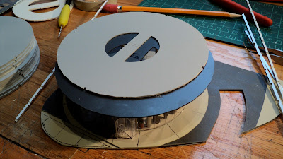
The below photo shows you what we're doing.  The top piece (painted a light grey rather than the stock white) is resting on top of the ceiling section of the ground floor lobby that we attached in the last step.

Note the semi-circle holes in these sections which MUST line up!

What I also needed to figure out was how to wire this thing. There doesn't appear to be an easily accessible cavity for the wiring, so the only choice is to create my own holes in an area that won't be conspicuous.
I decided to make two small holes in the area between the central elevator / core shafts.  You can see the holes below in the piece on the right next to the yellow hand drill.  I marked them slightly off- center  (to ensure alignment is consistent as each section is added) and then pre-drilled the holes.
Another important consideration at this point is interior detailing.  So I pretty much stopped working on the building and sliced up a lot of pieces of styrene, glued them together, painted them, and had a bunch of 'office cubicles' ready to apply to each floor as it was installed.
Back to lighting, I decided to light about 11 or so of the total 26 floors in the building.  Most floors would get two sets of 3 LED SMD strips.  Some floors would also get a third set of LED's just for variety.
Below is a photo of the ceiling of one of the floors to get 3 sets of LED's.  Note the wire, which I attempted to solder with as little slack as possible to avoid getting snagged on anything and to not be visible. 
I also added several LED strips into the interior of the lobby section that was already glued together.  Poor planning on my part actually as I should have done this in Step 2 as it would have been a lot easier.  Anyway, you can see the leads from the 3 LED strips streaming out of the top in the below photo.
Finally getting things where I need them for the lighting, section "Ec" is then given a bit of glue and then applied to the top of the black ceiling of the lobby.  Make sure the semi-circles are aligned!
Back to lighting again....there's an old (and likely dangerous) method of wiring houses here in the USA called "Knob and Tube" wiring.  I kind of take the same approach with distributing the power for the lighting of this building (used the same approach for lighting the "Skynet" building as well);  what I do is run two brass rods through the holes I drilled (see above) and therefore have a 'bus' of both positive and negative electricity running throughout the building.  I don't know if this is safe or a potential fire hazard, so before you do anything stupid and follow my advice, you should check with an electrician that knows better than you or I.
This method is very convenient for soldering the wire leads from the LED strips on each floor without having to run a billion wires through each floor.  

And that is a wrap of Step 3!  Next...Step 4!

For reference...
Here is Step 0 (Preparations)
Here is Step 1
Here is Step 2

10.17.2012

Luetke Office City Tower Build Step # 2


STEP 2

Okay, this is a relatively easy and short step!  So let's get on with Step 2!

The original German instructions;
2. Danach die schwarze Untersichtplatte Ea mit der kreis förmigen Nut auf die Fassade stecken unde fixieren. Die semicircle formigen Kernöffnungen mussen jetzt übereinander liegen.  Die acht 4mm starken stutzen werden nun von unten durch die Bodenplatte in die Untersichtplatte gesteckt und an der Bodenplatte verklebt.

And the somewhat incomprehensible English computer translation:
Then the black soffit plate Ea with the circular groove put on the facade fix under. The semicircle shaped core holes must now align. Clip the eight 4mm thick are now inserted from below through the base plate into the soffit plate and bonded to the bottom plate.

So what that means is that now you're going to take the circular piece labelled "Ea" and attach it to the top of the glass wall section we glued to the bottom level in Step 1.

Of course, its not that easy as you still have the difficult task of attempting to align the glass walls into a very thin circular groove.   Also be sure that the two semi-circle holes in both the roof and the bottom section are aligned! 

The second half of Step 2 is to insert the 4mm columns.  They come white, but I painted them (and other parts) with Model Masters "Aluminum Plate".   Again, this is simpler than it sounds as the columns fit very tightly into holes around the windows.  A trick I used is to run a thin brass tube (anything that is skinny enough to fit in the columns would work) through the columns to guide them into the holes on the other side.  Glue'em in and your done!
Okay...that's it for Step 2! Easy huh? ;=)

Next...Step 3!!!!

10.15.2012

Luetke Office City Tower Build Step # 1

STEP 1

After all the preparations from my last post we are now finally ready to follow the instructions!  As I mentioned in my first post on this project, all of the instructions are in German, and as I could find no 'digital copy' to paste into Google Translate, I had to re-type all of the German instructions into Microsoft Word, which I then could paste in Google Translate!

So here is Step 1 in the original German:


1. Die beiliegende kurze Glasfassade mit Turen fur die eingangshalle wird an den senkrechten nuten leicht nach hinten geknickt so dass die runder form stuckwise vorgebogen wird. die knicke anpassen, dass ein gleichmassiger kreis entsteht.  Anschliessend die fassade in die Nut der bodenplatte einsetzen, beginnend mit der Wand zwischen den Drehtüren, und ebenfalls mit wenig Kleber befestigen. 
Eventuell die lange der fassade angleichen damit keine Uberlappung an der stossfuge entsteht.
Zur Montage der Drehturen werden die durchsichtigen Drehkreuzwände verschränkt zu einem Kreuz zusammengesteckt und verklebt.  Dieses Kreuz auf die Nuten der Trommeltürdecke kleben.  Ebenso die Halbschalen in die Nuten kleben.  Nun konnen die Drehturen eingesetzt werden. Zur Gestaltung der Eingangshalle muss nun die Animierung mit Figuren und Möbel statfinden.
And here is the computer-translated English version, which is actually two steps:

  1. The accompanying short glass facade with doors for the entrance hall is on the vertical grooves bent slightly backwards so that the round shape stuckwise is pre-bent. Adjust the wrinkle that a bigger circle is created equal. Then the facade into the groove of the bottom plate attached, starting with the wall between the doors, and also with a little glue.

Any of the long facade align so that no overlap occurs at the joint.

To assemble the rotating doors, the transparent hub walls are put together through a cross and glued. The cross on the grooves of the drum door blanket stick. Also, the half shells stuck in the grooves. Now, the rotation can be used doors. To design the hall now has the animation statfinden with figures and furniture.


The first part of Step 1 is to glue the bottom floor windows into a circular groove in the bottom section.   You can make out where this groove is in the below photos as its the dividing line between the dark and light tan/concrete colors.  There are two sections of clear glass material; one section is for the ground floor the other is for the top floor.  The bottom floor has cut outs for the rotating doors.

The instructions advise to 'pre-bend' the clear plastic, and this is a good idea.  GENTLY bend it along the machined creases to approximate the diameter of the groove to which it will be glued.  Do this carefully as the plastic will snap and then you'll have to glue together a crease, which will be unsightly!
Once you've got the correct section of 'glass' for the bottom floor bent to the right diameter, its time to glue it in place.  Well, I wish I could say that this kit starts off easy, but this is actually pretty difficult.  It goes without saying that no matter how well you bend the plastic, getting the precise match to the groove is impossible.

To glue it, I used a different type of glue for this application - its called "Welder" and its a clear, gel-like glue that dries solidly but has a 'rubbery' feel.  I wanted to avoid a traditional plastic cement as it would smear the paint I've already applied and avoid "Super Glue" or cranoacrylate like the plague around clear plastic!  So I squeezed out some glue in a semi-circle on a post-it note and dipped the plastic into it.
 To help hold the plastic in place for a bit while the glue sets, I put a few strips of tape on the interior side of where the glass wall would go:
After some tense moments, I got half of the 'glass' seated into the groove (remember above when I said bend the plastic gently? Thus, this is why you only see a bit more than half installed at this time in the below photo!):
 A closer view...
Once I've got the glass seated (with glue) into the groove, I set a block of wood on it to ensure it STAYS in the groove while the glue sets.  I let it sit overnight just to be sure!
 The second part of Step 1 is to build and install the rotating doors.  This is a fairly simple task.  First, find the rectangular pieces with the notches in them and insert them into each other along the cut or notch sections.
The choice of adhesive for this step was Faller Super Expert.  This is more of plastic solvent type of glue, but I like it a lot as it comes in a container with a 'needle type' applicator which allows for a lot of control.  It also seems to work quite rapidly.  Apply just a tiny amount to the door sections along the groove to keep them solidly together.
Once the glue has set, attach the curved sections to either side of the doorway:
Once they've set, go ahead and insert them into the gaps in your glass wall, and apply a little glue to keep them in place.  I've yet to master precision glueing, so don't feel bad either if you can't get all the glue to be unnoticeable!
You can also tell from the above photo that I've added interior details.  The next step will involve glueing the ceiling/ roof to the top of the wall, so the chance to detail (and add lights!) is now!

Continued in Step 2....

10.13.2012

Luetke Office City Tower Build #0 (Preparations)

 STEP 0 (Preparation)

I purchased a Luetke Modellbahn "Office City Tower" 15 story building along with the 11 story extension a while back and have been both intimidated as well as procrastinating getting started on it.  Well, time to get started!  I decided (with a little urging from one of my friends found through this blog) to share my progress step by step.  So while I typically write about my buildings and experiences after the building is complete, in this case I'll be posting on my progress as I get various steps complete.

Or not. That's sort of the risk of this approach as I may get frustrated and stop!

Below is the primary 15 story kit, and below is the 11 story add-on kit:
The first step is to take a look at all the different parts in this somewhat intimidating kit.
What I realize very early on is that instructions are necessary.  Unfortunately, the instructions come only in German!  I therefore spent an hour manually re-typing the German instructions into Google Translate to attempt to come up with an English-language interpretation. 

So anyway, after reviewing the instructions (now in an almost coherent "English"!) and getting an idea for what all the various pieces do I start to plan how this will go (although its not entirely clear to me yet where/how the 11-story extension gets added ).

One of the first decisions I need to make is where this building will go when its finished and whether or not the rather large provided 'ground plate' will fit.  As it turns out, its rectangular shape really will not fit anywhere on the layout, so I decide to lose some of the features of the kit and shorten it to fit the angled section I expect this building to ultimately rest. 
The plate is a type of styrene like plastic and with multiple scores from the knife, it cuts fairly easily.
Then I have to make some decisions about what to paint, or not.  I've decided to keep the black/grey exterior...it actually has a nice patina and in the photos with this apparent stock color I think it looks really nice.  I do decide that may of the white pieces need some color.  For structural pieces I use Model Masters "Aluminum Plate".

I also need to paint the 'ground section' as it actually incorporates several different types of 'ground' that will best be colored at this stage.  There is the buildings interior floor, the surrounding sidewalk and pedestrian areas, and finally some grass/landscaping areas that complement the area.  With masking tape and some "Camouflage Grey" paint I first paint the color for the concrete sidewalks.
So there you are, several hours already into the project and I have yet to even start "Step 1" of the instructions!

10.08.2012

Street Markings (again)

A quick little post on adding street markings (hmmm....this sounds like a repeat!).  Well, as with last time, I used masking tape and white paint to create street markings for the station area. 
I tried using standard artist's white acrylic paint. Its obviously more of 'paste' than the more liquid white paints we typically use on the models, and I thought this extra thickness might help to avoid any bleed through under the masking tape.  I also sort of apply the paint in 'dry brush' fashion; you don't want to lump too much paint onto the street for the markings after all!
I still have some leftover rub-on decals from Faller and Busch to complement the basic stripes I have now, and I will apply some weathering to the street to lose that 'too-clean' look as well.

10.07.2012

2012 Layout Update Video!!!


This video is a sort of video over-view of a lot of the work that I've done on the layout for the past year.  So if you've been reading this blog, you'll likely have seen all of this covered before!  I have received a lot of requests to provide more insight into my buildings, so the focus is sort of on the new buildings I've either built or added in the past year.  Hope you enjoy!

10.04.2012

The Station Area Buildings

Well, I finally completed all of the facades for the station area and installed them on the layout.  I covered the structures in more depth in an earlier post, so I'll provide some minimal comments with the below photos.
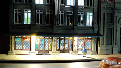
The above photo is the combination of two Artitec facades kit-bashed to form a taller building.  You can get a better sense of its increased height in the photo at the bottom.   The awning over the doorway is leftover from a TomyTec structure and I thought it might work well here.
These photos are more of the Artitec buildings.  The sidewalk is made from card stock...usually I use styrene but cardstock is both easier to work with (that is, easier to cut!) and cheaper.  Others have used to to good effect so I thought I wold give it a go.
While these are facades, I actually built them so that they go back about 10mm/ 3/4" so that the interiors appear to have some depth.  Given where these buildings are located, and the fact they are facades, I did virtually nothing in terms of interior detail.
The above facade is another Artitec kit, but it is a an HO kit.  As I mentioned in my earlier post, I cut out the HO sized doorway and substituted an entrance from my Walthers Hardwood Furniture structure.  Honestly, it turned out really well and has me thinking of more HO kits I can 'convert' in the future!
The "Chong Ching" establishment shown in the above photo is actually a real place near Gare de l'Est in Paris.  I thought the name and sign were kitschy and seemed like a suitable establishment to locate right across the street from the station.
This building is my homage to those classic 'sidewalk cafe' type restaurants.  More detail on this in my last post.

And finally, below is the 'street' itself across from the station.  It also provide s a good view (and one of the few photos that came out in decent focus!!!!) of the 'deconstructed' Arnold Universal building that become a small office tower with a giant "Miele" billboard on the roof. 
In addition to the first 'background structures' I made several months back (not shown in the above photo as the station tower is blocking them) I need a few more buildings to complete the scene.  I also need to get clever about creating depth at the road intersection shown in the above photo.  There are some interesting paper-based kits available from Scalescenes that I may work on next.

Finally, thanks to everyone for the nice comments.  Truly...THANK YOU! I know what an absolute PAIN the latest version of the "Capcha" security thing is....how annoying is that! Of course, anyone who has started a blog knows how quickly the ridiculous spammers will start posting if you don't have this sort of feature, but wow, its annoying!  Its an amazing test of patience and tenacity to write a comment these days!